Product Overview
FLUKE 120B (Model 120B) is a FLUKE supplied by Guangzhou Yunke Electronics Co., Ltd. FLUKE 120B — FLUKE · Yunke Electronics. Request a quotation and datasheet.
Brand: FLUKE | Category: FLUKE
Sales Inquiries: 15626018696 · 78403603@qq.com
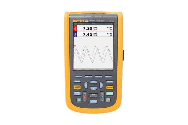
FLUKE 120B
Technical Specifications
| Frequency Response - DC Coupling | not Equipped With Probe and Test Test Lead (with BB120) 123B: DC Maximum 20 MHz (-3 dB) / 124B and 125B: DC Maximum 40 MHz (-3 dB) |
|---|---|
| Frequency Response - DC Coupling Equipped With STL120-IV 1:1 Display Test Test Lead | DC - 12.5 MHz (-3 dB) / DC - 20 MHz (-6 dB) |
| Frequency Response - DC Coupling Equipped With VP41 10:1 Probe | 123B: DC Maximum 20MHz (-3 dB) / 124B and 125B: DC Maximum 40 MHz (-3 dB) |
| Frequency Response - AC Coupling (Such As ) | not Equipped With Probe and Test Test Lead <10 Hz (-3 dB) |
| Frequency Response - AC Coupling (Such As ) Equipped With STL120-IV 1:1 Display Test Test Lead | <10 Hz (-3 dB) |
| Frequency Response - AC Coupling (Such As ) Equipped With VP41 10:1 Probe | <10 Hz (-3 dB) |
| Upper Time, Excluding Probe, | 123B <17.5 ns / 124B and 125B <8.75 ns |
| Input | not Equipped With Probe and Test Test Lead 1 MΩ / 20 pF |
| Input Equipped With BB120 | 1 MΩ / 24 pF |
| Input Equipped With STL120-IV 1:1 Display Test Test Lead | 1 MΩ / 230 pF |
| Input Equipped With VP41 10:1 Probe | 5 MΩ / 15.5 pF |
| Sensitivity | 5 mV to 200 V / div |
| Analog Bandwidth Limit Device | 10 kHz |
| Display Mode | A、-A、B、-B |
| Maximum Input Voltage A and B | Direct Input, Equipped With Test Test Lead, or Equipped With VP41 Probe 600 Vrms |
| Maximum Input Voltage A and B Equipped With BB120 | 600 Vrms |
| Terminal and Grounding Maximum Voltage | 600 Vrms |
| Indication Gauge Mode | Standard, Single a, Rotation |
| Range (Standard) | etc. Sampling 123B: 20 ns to 500 ns / div, |
| Range (Standard) Real-time Sampling | 1 μs to 5 s / div |
| Range (Standard) Single (Real-time) | 1 μs to 5 s / div |
| Range (Standard) Rotation (Real-time) | 1 s to 60 s / div |
| Sampling Rate (Dual Channel Same When Sampling) | etc. Sampling (Repeat Signal) Height up to 4 GS / s |
| Sampling Rate (Dual Channel Same When Sampling) Real-time Sampling 1 μs to 60 S / Div | 40 MS / s |
| Display More | Automatic , Trigger |
| Data Source | A,B |
| A and B Sensitivity | @ DC - 5 MHz 0.5 div or 5 mV |
| @ 40 MHz | 123B: 4 div |
| @ 60 MHz | 123B: N / A |
| Rate | Correction Value, Value |
| Display Mode | Normal Length up to 25 ns Wave , Display Class Analog Signal Continuous Wave |
| Display Mode | Control Wave Noise |
| Display Mode | not Sampling Wave |
| Display Mode Package | Recording and Display a Range Time internal Wave Minimum and Maximum |
| Automatic Setting (Connect-and-View™) | Full Automatic Continuous Adjustment cells Width Value, when , Trigger Logic Level, Trigger Interval and Trigger. User via Adjustment Width Value, when or Trigger Logic Level can Manual Over . |
| Range | 500 mV、5 V、50 V、500 V、750 V |
| Accuracy | ±(0.5% +5 counts) |
| Total Than (CMRR) | >100 dB @ dc, >60 dB @ 50, 60 or 400 Hz |
| Full Scale Reading | 5000 Counting |
| Range | 500 mV、5 V、50 V、500 V、750 V |
| Accuracy Range 5% - 100% (DC Coupling) | DC - 60 Hz (V ac+dc) ±(1% +10 counts) |
| Accuracy Range 5% - 100%(DC Coupling) 1 Hz - 60 Hz (V Ac) | ±(1% +10 counts) |
| Accuracy Is Range 5% - 100% (AC or DC Coupling) | 60 Hz to 20 kHz ±(2.5% +15 counts) |
| DC (Only VAC) | >50 dB |
| Total Than (CMRR) | >100 dB @ dc |
| Full Scale Reading | 5000 Counting, Reading and Signal Wave Number No . |
| Mode | Maximum Peak, Minimum Peak, or Peak |
| Range | 500 mV、5 V、50 V、500 V、2200 V |
| Accuracy | Maximum Peak or Minimum Peak Accuracy Full Scale 5% |
| Accuracy Peak Accuracy | Full Scale 10% |
| Full Scale Reading | 500 Counting |
| Range | 123B: 1 Hz, 10 Hz, 100 Hz, 1 kHz, 10 kHz, 100 kHz, 1 MHz, 10 MHz and 50 MHz |
| Frequency Range | Continuous Automatic Setting in is 15 Hz (1 Hz) to 50 MHz |
| 1 Hz to 1 MHz Accuracy | ±(0.5% +2 counts) |
| Full Scale Reading | 10000 times |
| Maximum Reading | 50.00 kRPM |
| Accuracy | ±(0.5% +2 counts) |
| Range | 2% to 98% |
| Frequency Range | Continuous Automatic Setting in is 15 Hz (1 Hz) to 30 MHz |
| Frequency Range | Continuous Automatic Setting in is 15 Hz (1 Hz) to 30 MHz |
| Full Scale Reading | 1000 Counting |
| Equipped With Current | Range and V dc, V ac, V ac+dc or PEAK Phase Same |
| Equipped With Current Than Number | 0.1 mV / A、1 mV / A、10 mV / A、100 mV / A、400 mV / A、1 V / A、10 mV / mA |
| Equipped With Current Accuracy | and V dc, V ac, V ac+dc or PEAK Phase Same (plus above Current Clamp not Accuracy Setting degrees) |
| Range | 200 °C / div (200 °F / div) |
| Than Number | 1 mV / °C and 1 mV / °F |
| Accuracy | and V dc Phase Same (plus above Temperature Probe not Accuracy Setting degrees) |
| 0 dBV | 1 V |
| 0 dBm (600 Ω / 50 Ω) | 600 Ω or 50 Ω Reference Conditions under is 1 mW |
| dB on | V dc, V ac or Vac+dc |
| Full Scale Reading | 1000 Counting |
| Range | 1 to 10 |
| Full Scale Reading | 90 Counting |
| Mode | A - B,B - A |
| Range | 0 to 359 degrees |
| Resolution | 1 degrees |
| Configuration | Single Phase / three Phase three Wire Balance Load (three Phase: only Limit Wave Division Quantity, only Limit “ Automatic Setting ” Mode) |
| Power Number (PF) | and Range than Rate - 0.00 to 1.00 |
| Specification | Use Input A() and Input B(Ampere) Phase Sampling Value Phase to RMS Reading |
| Full Scale Reading | 999 Counting |
| VA | Vrms x Arms |
| VA Full Scale Reading | 999 Counting |
| No Power (VAR) | √((VA)²-W²) |
| No Power (VAR) Full Scale Reading | 999 Counting |
| Specification | Measurement Width Adjustment Control Signal, e.g. such as Electric Unit Driver Device Output Signal |
| Management | Reading Display Yes at Wave Frequency pcs Period Number Sampling Average Effective Voltage |
| Accuracy | Correction Wave Signal Vrms |
| Range | 123B and 124B 500 Ω, 5 kΩ, 50 kΩ, 500 kΩ, 5 MΩ, 30 MΩ |
| Range 125B | 50 Ω、500 Ω、5 kΩ、50 kΩ、500 kΩ、5 MΩ、30 MΩ |
| Accuracy | ±(0.6% + 5 counts)50 Ω ±(2% + 20 counts) |
| Full Scale Reading | 50 Ω to 5 MΩ - 5000 Counting, 30 MΩ - 3000 Counting |
| Measuring Current | 0.5 mA to 50 nA, with Range Increment Large and minus Small |
| Voltage | <4 V |
| Specification | <(30 Ω ± 5 Ω), at 50 Ω Range when |
| Measuring Current | 0.5 mA |
| Detection to | ≥1 ms |
| Measuring Voltage | 0.5 mA when >2.8 V |
| Measuring Voltage When | <4 V |
| Measuring Current | 0.5 mA |
| Extreme | Input A is + Extreme, COM is - Extreme |
| Range | 50 nF、500 nF、5 μF、50 μF、500 μF |
| Full Scale Reading | 5000 Counting |
| Measuring Current | 500 nA to 0.5 mA, with Range Increment Large and Increment plus |
| Zero Setting | Reference Value Setting Actual Value |
| Automatic Hold (Input A) | and Hold Setting Measurement . Measurement Setting when Output . Automatic Hold Functions Applicable at Main Instrument Gauge Reading, its in AC Signal Value is 1 Vpp, DC Signal Value is 100 mV. |
| Fixed Small Number Point | Operating minus Key Use |
| Data Source | A,B |
| Single Wire | Average Reading, Minimum Reading and Maximum Reading |
| Dual Wire | Peak, Time Distance and Time Distance Number Reading |
| Dual Horizontal Wire | Height, Low and Peak Reading |
| Upper or Lower Time | Over Time, 0% and 100% Reading (Manual or Automatic Adjustment Flat; Single Channel Mode |
| Accuracy | and Indication Wave Gauge Accuracy Phase Same |
| Measuring Speed | Maximum 2 pcs Measured values / s |
| Recording Large Small (Minimum Value, Maximum Value, Average) | 1 2 M Reading |
| Recording Time Degree | See the original manufacturer datasheet |
| Maximum Part Quantity | 1024 |
| Maximum Sampling Rate | 400 K Sampling / s |
| Large Small Internal | 400 M Sampling Recording Time |
| Degree Internal | 500 μs / div is 15 minutes / 20 ms / div is 11 hours |
| Recording Large Small SD | 1.5 G Sampling |
| Recording Time Degree SD | 500 μs / div is 11 hours / 20 ms / div is 14 |
| Maximum Part Quantity | 64 |
| Reading | W、VA、var、PF、DPF、Hz |
| W, VA, Var Range (Automatic) | 250 W to 250 MW, 625 MW, 1.56 GW |
| W, VA, Var Range (Automatic) When: Total (% R) | ±(2% + 6 counts) |
| W, VA, Var Range (Automatic) When: (% F) | ±(4% + 4 counts) |
| DPF | 0.00 to 1.00 |
| Power Series Number | 0.00 to 1.00, ±0.04 |
| Frequency Range | 10.0 Hz to 15.0 kHz / 40.0 Hz to 70.0 Hz |
| Number | DC - 51 |
| Reading / Light Reading | Vrms / Arms / W can by Selection Wave each times Harmonic by Single pcs Reading |
| Type | Type Protocol |
| AS-i | NEN-EN50295 |
| CAN | ISO-11898 |
| Interbus S | RS-422 EIA-422 |
| Modbus | RS-232 RS-232 / EIA-232 |
| Modbus RS-485 | RS-485 / EIA-485 |
| Foundation Fieldbus | H1 61158 No. 1 Class, 31.25 kBit |
| Profibus | DP EIA-485 |
| Profibus PA | 61158 No. 1 Class |
| Display | Type 5.7 in with Source TFT |
| Display Resolution | 640 x 480 pixels |
| Display | Direct 10 division 40 pcs pixels |
| Display Horizontal | 12 division 40 pcs pixels |
| Power | External via BC430 AC Adapter |
| Power Input Voltage | 10 V DC to 21 V DC |
| Power Power Consumption | 5 W Standard |
| Power Input Connection Device | 5 mm Base |
| Power Internal Part | via BP290 Battery groups |
| Power Battery Power Supply | 10.8 V Rechargeable Battery |
| Power Operating Time | 7 hours (50% Backlight degrees) |
| Power Charging Time | Test Tool when is 4 hours |
| Power Environment Temperature | Charging when is 0 to 40°C(32 to 104°F) |
| Data Storage | internal Part Memory Device Memory 20 pcs Data Micro Type SD Caliper Groove, with with optional SD Caliper |
| Unit | Dimensions 259 x 132 x 55 mm |
| Unit Weight | 1.4 kg (3.2 lb), incl. battery |
| Interface | Light Interface Transfer Display Screen Diagram (digits Diagram), Setting and Data |
| Interface USB Interface, Can Connection PC / Electric | OC4USB Light Electric USB Adapter / Cable (Optional), Operating Windows® Version |
| Interface Optional WiFi Adapter | will Display Screen Diagram (digits Diagram), Setting and Data Transfer to PC / This Electric , Flat Plate Electric , Smart Unit etc.. Provided USB Port, Use at Connection WiFi Connection Device. Output at Safety Considering, not via Connection Wire Operating USB Port. |
| Operating Environment | MIL-PRF-28800F 2 Class |
| Temperature | Operating Battery Operating 0 to 40°C(32 to 104°F) |
| Temperature Operating AC Adapter Operating | 0 to 50°C(32 to 122°F) |
| Temperature Storage | -20 to 60°C(-4 to 140°F) |
| Operating Humidity | 0 to 10°C(32 to 50°F) when non-condensing |
| Operating Humidity 10 to 30°C(50 to 86°F) When | 95% |
| Operating Humidity 30 to 40°C(86 to 104°F) When | 75% |
| Operating Humidity 40 to 50°C(104 to 122°F) When | 45% |
| Storage | -20 to 60°C(-4 to 140°F) non-condensing |
| Altitude | Operating Altitude is 3 km(10,000 ft) CAT III 600 V |
| Altitude Operating Altitude Is 2 Km (6,600 ) | CAT IV 600 V |
| Altitude Storage | 12 km (40,000 feet) |
| EMC EMC Compatibility | Standard IEC 61326-1: , CISPR 11: |
| EMC EMC Compatibility (KCC) | A Class Device ( and Communication Device) |
| EMC EMC Compatibility United States (FCC) | 47 CFR 15 B Part Division. per No. 15.103 records Gauge Setting, This Product by is Device. |
| with Adapter Wireless Electric | Frequency Range 2412 MHz to 2462 MHz |
| with Adapter Wireless Electric Output Power | <100 mW |
| IP Rating | IP51, : EN / IEC60529 |
| Safety Class | General-purpose IEC 61010-1: Pollution Degree 2 |
| Safety Class Measuring | IEC 61010-2-033:CAT IV 600 V / CAT III 750 V |
| Maximum Input Voltage A and B | Direct Input or via Circuit Input 600 Vrms CAT IV |
| Maximum Input Voltage A and B Equipped With Banana-to-BNC Adapter BB120 | 600 Vrms |
| Maximum Input Voltage A and B Terminal and Grounding Maximum Voltage | 600 Vrms Cat |
Some specification lines are quoted from the original manufacturer datasheet. Numbers, units and model codes are preserved verbatim; an English datasheet is available on request.
Product Description
Product Overview
Specifications: Fluke Connect-and-View RS-232 i400S 120 125 51 14 123 124 20 40 10 1 VA PF DPF THD SD CAN PC. Please contact our engineers for the full technical wording. Reference values: 120, 125, 40.
Key Advantages
- Double-in digital wavewatch and multi-mean watch
- 40 MHz or 20 MHz wave scale width
- Two tables with valid digital values for 5,000
- Connect-and-ViewTM triggers simple and easy to use without manual operation
- IntelellaSetTM technology can read and read values based on the automatic intelligent adjustment of the signal.SurverageSScrets
- Double-circuit waveform and instrument reading recorders that allow trend analysis of long-term data
- Amiterit oxidation captures an unsettled intermittent signal up to 4 kHz.s
- Sphere strap shield test fuses that can be used to conduct electrical resistance and breakout measurements
Category Description
The field-based stowage table, combined with a omnibus and stoke-stoking function, is suitable for the industrial field-based stoker and bus signal diagnosis..Stores and bus-line signal diagnosis
Applied industry & test project
- Industry: Industrial equipment overhaul, site commissioning, electrical installation and maintenance, scientific research institutes
- Application: double input digital wavewatches and multi-purpose tables; 40 MHz or 20 MHz wave scale width; real value figures for two 5,000 digits
FAQ
Q: FLUKE Fluke 120B portable oscillator, what can you do?
A: FLUKE Fluke 120B Portable oscillator product FLUKE Fluke. X-Oxyst X-Oxyst-SpID X- . X- -E The main functions listed officially include: double input digital signalometers and multi-purpose tables; 40 MHz or 20 MHz frequency width; and two tables with real valid value figures for 5,000 digits. If the type is selected according to working conditions, the measurement object and process requirements may be provided and confirmed with cloud assistance
Q: What are the key technical indicators for 120B?
A: This page is based on official information and contains a total of 193 items covering wavewatch mode/vertical/level/trigger. For more detailed accuracy and environmental conditions, please refer to the official manual, which is not open on an article-by-article basis
Q: How can the selection and the cargo date be confirmed?!
A: Guangzhou Yunke Electronics Co., Ltd. supplies a full range of FLUKE Fluke products, which can provide selective advice, technical information and post-sale support. Please provide a specific model, quantity and usage profile, which will be confirmed with the assistance of staff
Q: What is the category of the FLUKE Fluke 120B portable oscillator? What are the scenarios?
A: This product is a portable wave sign (FLUKE Fluke/ Portable waver). On-site, a table with a master table and a waver function is suitable for industrial field speeders and bus signal diagnosis
Q: How can technical support be obtained after purchase?!
A: Products with official instructions and quality assurance services; Guangzhou Yunke Electronics Co., Ltd. provides pre-sale selection and post-sale coordination services, which can be submitted through site contact, supported by staff assistance to connect to the original plant
Reference values from the original datasheet: 120, 120, 125, 125.
All model codes, numbers and units are preserved verbatim from the original manufacturer datasheet. An English datasheet is available on request.
For a quotation, lead time or an optional calibration certificate, please contact our engineers.
Related Products
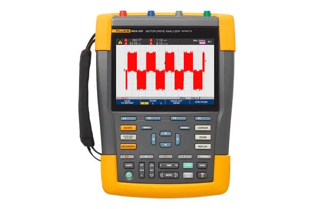
FLUKE MDA-550
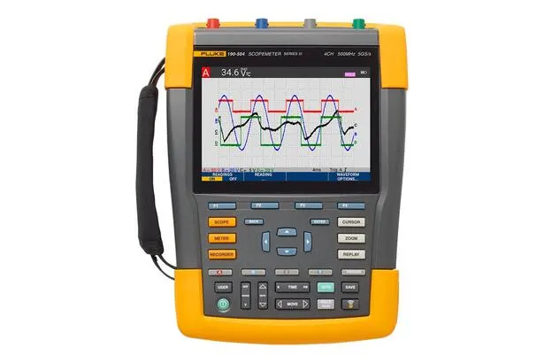
FLUKE 190-062/190-064/190-104/190-204
FLUKE P5551
FLUKE P5544
FLUKE P5543