Product Overview
FLUKE MDA-550 (Model MDA-550) is a FLUKE supplied by Guangzhou Yunke Electronics Co., Ltd. FLUKE MDA-550 — FLUKE · Yunke Electronics. Request a quotation and datasheet.
Brand: FLUKE | Category: FLUKE
Sales Inquiries: 15626018696 · 78403603@qq.com
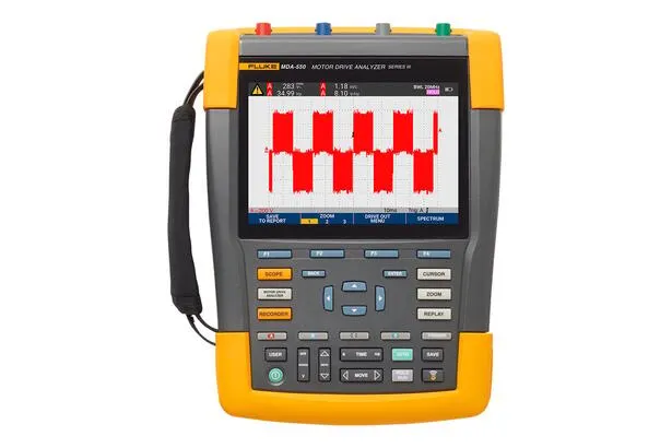
FLUKE MDA-550
Technical Specifications
| Test Point | Division groups Reading 1 Reading 2 Reading 3 Reading 4 |
|---|---|
| Phase - Phase | V-A-Hz V ac+dc A ac+dc Hz |
| Phase - Phase V Peak | V peak max V peak min V pk-to-pk Peak Series Number |
| Phase - Phase A Peak | A peak max A peak min A pk-to-pk Peak Series Number |
| Phase - Place | V-A-Hz V ac+dc A ac+dc Hz |
| Phase - Place V Peak | V peak max V peak min V pk-to-pk Peak Series Number |
| Phase - Place A Peak | A peak max A peak min A pk-to-pk Peak Series Number |
| Voltage | V ac+dc V ac+dc V ac+dc |
| Voltage Peak | V pk-to-pk V pk-to-pk V pk-to-pk |
| Current | A ac+dc A ac+dc A ac+dc |
| Current Peak | A pk-to-pk A pk-to-pk A pk-to-pk |
| DC | V dc V pk-to-pk V peak max |
| Specification | V ac V pk-to-pk Hz |
| Voltage and Current ( Filtering) | V-A-Hz V PWM A ac+dc Hz V / Hz |
| Voltage and Current ( Filtering) V Peak | V peak max V peak min V pk-to-pk Peak Series Number |
| Voltage and Current ( Filtering) A Peak | A peak max A peak min A pk-to-pk Peak Series Number |
| Voltage | V PWM V PWM V PWM |
| Voltage Peak | V pk-to-pk V pk-to-pk V pk-to-pk |
| Current | A ac+dc A ac+dc A ac+dc |
| Current Peak | A pk-to-pk A pk-to-pk A pk-to-pk |
| Phase - Phase | Zoom 1 V PWM V pk-to-pk Hz V / Hz |
| Phase - Phase Zoom 2 | V peak max V peak min Voltage Increment Quantity |
| Phase - Phase Peak Zoom 3 | V peak max Voltage Increment Quantity / s Peak above Time Over |
| Phase - Phase Zoom 3 Class | Voltage Increment Quantity Voltage Increment Quantity / s above Time Horizontal Over |
| Phase - Place | Zoom 1 V PWM V pk-to-pk V peak max V peak min |
| Phase - Place Zoom 2 | V Peak max V peak min Voltage Increment Quantity Hz |
| Phase - Place Peak Zoom 3 | V Peak max Voltage Increment Quantity / s Peak above Time Over |
| Phase - Place Zoom 3 Class | Voltage Increment Quantity Voltage Increment Quantity / s above Time Horizontal Over |
| Phase-DC + | Zoom 1 V PWM V pk-to-pk V Peak max V peak min |
| Phase-DC + Zoom 2 | V peak max V peak min Voltage Increment Quantity Hz |
| Phase-DC + Peak Zoom 3 | V peak max Voltage Increment Quantity / s Peak above Time Over |
| Phase-DC + Zoom 3 Class | Voltage Increment Quantity Voltage Increment Quantity / s above Time Horizontal Over |
| Phase-DC - | Zoom 1 V PWM V pk-to-pk V peak max V peak min |
| Phase-DC - Zoom 2 | V peak max V peak min Voltage Increment Quantity Hz |
| Phase-DC - Peak Zoom 3 | V peak max Voltage Increment Quantity / s Peak above Time Over |
| Phase-DC - Zoom 3 Class | Voltage Increment Quantity Voltage Increment Quantity / s above Time Horizontal Over |
| Voltage and Current ( Filtering) | V-A-Hz V PWM A ac+dc Hz V / Hz |
| Voltage and Current ( Filtering) V Peak | V peak max V peak min V pk-to-pk Peak Series Number |
| Voltage and Current ( Filtering) A Peak | A peak max A peak min A pk-to-pk Peak Series Number |
| Voltage | V PWM V PWM V PWM |
| Voltage Peak | V pk-to-pk V pk-to-pk V pk-to-pk |
| Current | A ac+dc A ac+dc A ac+dc |
| Current Peak | A pk-to-pk A pk-to-pk A pk-to-pk |
| Phase - Phase | Zoom 1 V PWM V pk-to-pk Hz V / Hz |
| Phase - Phase Zoom 2 | V peak max V peak min Voltage Increment Quantity |
| Phase - Phase Peak Zoom 3 | V peak max Voltage Increment Quantity / s Peak above Time Over |
| Phase - Phase Zoom 3 Class | Voltage Increment Quantity Voltage Increment Quantity / s above Time Horizontal Over |
| Phase - Place | Zoom 1 V PWM V pk-to-pk V peak max V peak min |
| Phase - Place Zoom 2 | V peak max V peak min Voltage Increment Quantity Hz |
| Phase - Place Peak Zoom 3 | V peak max Voltage Increment Quantity / s Peak above Time Over |
| Phase - Place Zoom 3 Class | Voltage Increment Quantity Voltage Increment Quantity / s above Time Horizontal Over |
| Shaft Voltage | pcs V pk-to-pk |
| Shaft Voltage Part | Voltage Increment Quantity above / under Time Voltage Increment Quantity / s pcs / s |
| Specification | Voltage V ac V fundamental Hz fundamental% THD |
| Current | A ac A fundamental Hz fundamental THD / TDD Percent |
| Measuring Functions | Specifications |
| Maximum Voltage, 10:1 or 100:1 Probe | 1000 V |
| Operating 10:1 or 100:1 Probe at Maximum Resolution (Grounding Voltage) | 1mV / 10mV |
| Full Scale Reading | 999 counts |
| 4 S to 10 Us / Div at Accuracy | ±(1.5% + 6 counts) |
| Operating 10:1 or 100:1 Probe at Maximum Voltage (Grounding Voltage) | 1000 V |
| Operating 10:1 or 100:1 Probe at Maximum Resolution | 1 mv / 10 mV |
| Full Scale Reading | 999 counts |
| DC to 60 Hz | ±(1.5% + 10 counts) |
| 60 Hz to 20 kHz | ±(2.5% + 15 counts) |
| 20 kHz to 1 MHz | ±(5% + 20 counts) |
| 1 MHz to 25 MHz | ±(10% + 20 counts) |
| Application | Measurement Width Adjustment Control Signal, e.g. such as Electric Unit Driver Device Device Output Signal |
| Management | Reading Display Yes at Basic Frequency pcs Period Number Sampling Average Effective Voltage |
| Accuracy | and Correction Wave Signal Vac+dc Phase Same |
| Mode | Maximum Peak, Minimum Peak, or |
| Operating 10:1 or 100:1 Probe at Maximum Voltage (Grounding Voltage) | 1000 V |
| Operating 10:1 or 100:1 Probe at Maximum Resolution | 10 mV |
| Maximum Peak, Minimum Peak | ± 0.2 div |
| Specification | ± 0.4 div |
| Full Scale Reading | 800 counts |
| Range | and V ac, Vac+dc or V peak Phase Same |
| Than Number | 0.1 mV / A、1 mV / A、10 mV / A、20 mV / A、50 mV / A、100 mV / A、200 mV / A、400 mV / A |
| Accuracy | and Vac, Vac+dc or V peak Phase Same (plus Current Clamp Accuracy) |
| Range | 1.000 Hz to 500 MHz |
| Full Scale Reading | 9999 counts |
| Accuracy | ±(0.5% + 2 counts) |
| Application | Display at AC Electric Unit Driver Device above Measure V PWM Value (See V PWM) except by Basic Frequency |
| Accuracy | % Vrms + % Hz |
| Application | Display a Phase digits Voltage except by 3 pcs True RMS Voltage Average Percent Maximum Difference Value |
| Accuracy | at Vac+dc Value Indication Property Percent |
| Application | Display a Phase digits Voltage except by 3 pcs Width Adjustment Control Voltage Average Percent Maximum Difference Value |
| Accuracy | at V PWM Value Indication Property Percent |
| Application | Display a Phase digits Current except by 3 pcs AC Current Value Average Percent Maximum Difference Value |
| Accuracy | at Aac+dc Value Indication Property Percent |
| Application | Display a Phase digits Current except by 3 pcs AC Current Value Average Percent Maximum Difference Value |
| Accuracy | at A ac Value Indication Property Percent |
| Reading | Voltage Difference (dV), when Difference (dt), Voltage Difference except by Time Difference (dV / dT), Over |
| Accuracy | and Indication Wave Device Accuracy Phase Same |
| Specification | DC to 51 times |
| Range | 1…9 kHz, 9-150 kHz(20 MHz Filtering Device Open), to 500 MHz(Voltage Adjustment Control) |
| Part / | at above and under Time ( Discharging) Measurement Indication Property Percent |
| Display Quantity | in can by Typical 50 Display Screen (Depends on Pressure than) |
| Transfer to Electric | Operating 32 GB or more Small 2 GB U Disk or mini-USB Rotation USB Data Cable or WiFi Connection Functions and Applicable at ScopeMeter® FlukeView™ 2 |
| Voltage Probe | 1:1、10:1、100:1、1000:1、20:1、200:1 |
| Current | 0.1 mV / A、1 mV / A、10 mV / A、20 mV / A、50 mV / A、100 mV / A、200 mV / A、400 mV / A |
| Shaft Voltage Probe | 1:1、10:1、100:1 |
| Specification | IEC 61010-1: Pollution Degree 2 |
| Measuring | Measurement Standard IEC 61010-2-030: CAT IV 600 V / CAT III 1000 V |
| Terminal and Grounding Terminal Maximum Voltage | 1000 V |
| Maximum Input Voltage | via VPS410-II or VPS421 1000 V CAT III / 600 V CAT IV |
| BNC Input | A, B, C, D Direct 300 V CAT IV |
| Maximum Voltage, Test Tool or with VPS410-II / VPS421 Voltage Probe Test Tool | from Terminal to Grounding Terminal is 1000 V CAT III / 600 V CAT IV; Terminal is 1000 V CAT III / 600 V CAT IV |
| Probe Tip and Probe Reference Wire Operating Voltage | VPS410-II:1000 V / VPS421: 2000 V |
Some specification lines are quoted from the original manufacturer datasheet. Numbers, units and model codes are preserved verbatim; an English datasheet is available on request.
Product Description
Product Overview
The use of pilot test settings and automated drive measurements to provide reliable and re-readable test results makes the failure of the power drive simpler..Spw!.Sp.SSSSSS The Fluke MDA-550 series III power drive analyser not only saves time and avoids the trouble of setting complex measurements, but also simplifys the power drive failure process. Just one test, and then the next step-by-step guide measurements show where you need to build voltage and current connections, and, at the same time, — Predefined measurements configurations ensure that you collect all the data you need for each key power drive, from input to output, straight flow bus and the power system itself. From basic to advanced measurements,.Screen_Telemetry from basic to advanced measurements,Screen MDA-550 provides full coverage and, using the built-in report generator, you can quickly, easily and confidently generate pre- and post-calculation reports. MDA-550 is the ideal portable power drive analysis test tool to help you safely identify and remove common problems in the power reverse drive system. The main parameters of the power drive are measured, including voltage, current, etc. Direct bus voltage level and communication twirling, voltage and current imbalance harmonised waves, voltage modem and power axle voltage discharge. Execute extended harmonic measurements to determine the effect of low and high harmonic waves on your power system. Execute pilot measurements,_Fres_Fres_Fres_Fres_Fres_Fres_Fres_Fres_Fo_Fo_Fo_Fo_Fo_F_F_ A graphical step voltage and current connection map is used to measure motor drive input, straight bus, drive output, motor input and axials. Using simplified measurement settings and preset measurement configurations,_._._. Automatically trigger data collection according to the selected test program. Create reports quickly and easily, especially for recording failure-refusal logs and for collaborating with others. Measuring additional electrical parameters,.Screech Screech_Screech_Treats_Scope_Text_Scope_Functions_Scope_Scope_Scope_Text_Text_Text_Treat_Scance_Treatment_ Comprehensive electrical and electronic measurements of industrial systems are carried out with the full 500 MHz oscillator, volume table and record function.Ass Fluke MDA-550 power drive analyser uses lead test measurements, making it easier to analyse the analysis than ever before. drive input by measuring input voltage and currents. Then compare the nominal voltage of the drive with the actual supply voltage, and it is quick to see whether the value is within acceptable limits. Then, check the input current and determine whether it is within maximum quota range._ and the appropriate guidance line specification. You can also check whether the harmonic loss is within acceptable levels by looking at wave shapes or by looking at the harmonic spectrum screen that shows both total harmonic loss and individual harmonic loss._ The voltage and current imbalance check the pressure imbalance on the input end to ensure that the phase imbalance is not too high (> 6-8 per cent) and that the phase rotates correctly. You can also check the current imbalance because excessive imbalance may indicate a problem with the drive flower. Extending the harmonic measure is a threat not only to the safety of the rotating machine but also to other devices connected to the power system._ MDA-550 can detect the harmonics of the power drive and the possible effects of the reverse switch. MDA-550 has three harmonic ranges, 1 to 51 sub-mixes, 1 to 9 kHz and 9 kHz to 150 kHz, capable of detecting any harmonic contamination. Communication-direct flow conversion within the drive is essential, and to achieve optimal drive performance, the pressure must be correct, filtered adequately and maintain low-line wave levels. High-twice voltage indicates that the capacitors have malfunctioned or that the connected power units are not specified correctly. The record function can be used to dynamically check the performance of the straight flow bus in the working mode of load-connected transport. Drive output Checks drive output with a focus on measuring voltage frequency ratios (V/F) and voltage mode._ The electrical power can be overheating when the value of the V/F ratio is high. When the V/F ratio is low, the connected power unit may not be able to provide the torque required on the load, thereby not fully running the expected process._ Pressure modem The measurement of the pulse width modem signal is used to check peaks of high voltage that may damage the insulation of the electrical circuit._ The time or steepness of the pulse is expressed by the dV/dt readings (power changes over time) that should be compared to the specified insulation values of the power. These measurements can also be used to determine the frequency of switches,_ To determine whether there is a potential problem with the electronic switch or the place of connection when the signal floats up or down. It is essential that electrical input ensure that the end is connected to the voltage for the power, and the rational choice of the wire between the drive and the power is equally crucial._ The wrong layout choices can cause the drive and the power to be damaged by the high voltage peak. It is important to check whether the current on the end is within the range of the power rating, because the high current can cause the power to overheating._ And thus shortening the life of the fixed sub-insulation, which causes early malfunctioning of the power system, the power pulse from the transformer can be coupled between the electron and the rotor, which leads to voltage on the rotor._ When such rotor power exceeds the insulation capacity of the axle lubricant, a flash current (fireflake) may occur, leading to point and sink erosion of the axis coil, which may cause premature failure of the conductor._ MDA-550 with carbon fibre brushes allows easy detection of destructive flash currents, while pulse amplification and event counting functions enable you to take measures before a failure occurs..Scope Add this attachment to enable you to detect potential damage without investing in expensive permanent installation solutions. Step-by-step pilot measurements ensure that you have the data required by MDA-550 to help you quickly, quickly and quickly. You can easily configure the analyser and get the drive measurements you need.! This allows for a quick and better maintenance decision. From power input to installed power units, the measurement function provided by MDA-550 allows you to remove the power drive at the most rapid speed possible..Scope-free driveSceneScancer Quiana step-by-step Quest Quest ♪ ♪ endedwayowsir oxy-di-di-di-di-di-di-di-di-di-di-di-di-di-di-di-di-di-di-di-di-di-di-di-di-di-di-di-di-di-di-di-di-di-di-di-di-di-di-di-di-di-di-di-di-di-di-di-di-di-di-di-di-di-di-di-di-di- Dalque with lumtite gel + + + + + + + + + + + + + + + + + + + + + + + + + + + + + + + + + + + + + + + + + + + + + + + + + + + + + + + + + + 1 Block BP 291 Lithium ion battery 1 BC190 charger/power adapter 3 ZX ZX ZX ZX ZX XT XXT Q20 100: 1 high pressure probe, QuembH Quest Quiz Agry alligator folder 1 Root VPS410-II-R 10: 1 500MHz electrical probe 3 ZX21 electrical communications XV Communication T Tiles 1 set of SVS-500 Axis voltage Measurement Package (3 electric brushes) Constellation shelf 2 extended poles and magnets with wheels large size protection portable box (C437-II) ) FlukeView-2 PC Software (full version)Pilo -Step-Step-Teams-Step-Te. Reference: VPS421, i400s, 9 kHz, 150 kHz
Key Advantages
- Guide testing by graphical step-by-step connection diagram
- Preset measurement configuration files reduce the complexity of settings
- Internal reporting function%
- Easy generation of pre- and post-adjustment troubleshooting reports
Category Description
The field-based stowage table, combined with a omnibus and stoke-stoking function, is suitable for the industrial field-based stoker and bus signal diagnosis..Stores and bus-line signal diagnosis
Applied industry & test project
- Industry: Industrial equipment overhaul, site commissioning, electrical installation and maintenance, scientific research institutes
- Application: leading tests by graphical step-by-step connectivity maps; predefined measurement configuration files reduce the complexity of settings; built-in report writing function
FAQ
Q: FLUKE Fluke MDA-550 portable oscillator, what can be done primarily? Q: Q: FLUKE MDA-550er
A: FLUKE Fluke MDA-550 portable oscillator product FLUKE Fluke. X-X-X-X-XX. X-V-V-V-V-V-X-X-X-X-X-X-X-X-X-X-X-X- The main functions listed officially include: leading tests by graphical step-by-step links; predefined measurements profile files reduce the complexity of settings; and built-in report writing functions. If you need a work-by-work selection, you can provide measurement objects and process requirements._ Confirmed with the assistance of Clouds Section.!
Q: What are the key technical indicators for MDA-550?
A: The list of parameters for this page has been compiled by official information and contains a total of 110 items covering the measurement and analysis of the mix/electric drive input/voltage and current/electric drive bus.A.. For more detailed accuracy and environmental conditions, please refer to the official manual and this page is not open article by article.!
Q: How can the selection and the cargo date be confirmed?!
A: Guangzhou Yunke Electronics Co., Ltd. supplies a full range of FLUKE Fluke products, which can provide selective advice, technical information and post-sale support. Please provide a specific model, quantity and usage profile, which will be confirmed with the assistance of staff
Q: What is the category of the FLUKE Fluke MDA-550 portable oscillator? Which scenes are applicable? Q.15501Q portable osculator?
A: This product is a portable wave sign (FLUKE Fluke/ Portable waver). On-site, a table with a master table and a waver function is suitable for industrial field speeders and bus signal diagnosis
Q: How can technical support be obtained after purchase?!
A: Products with official instructions and quality assurance services; Guangzhou Yunke Electronics Co., Ltd. provides pre-sale selection and post-sale coordination services, which can be submitted through site contact, supported by staff assistance to connect to the original plant
All model codes, numbers and units are preserved verbatim from the original manufacturer datasheet. An English datasheet is available on request.
For a quotation, lead time or an optional calibration certificate, please contact our engineers.
Related Products
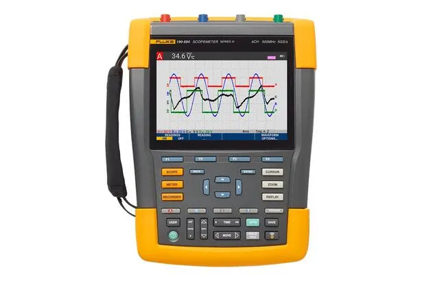
FLUKE 190-062/190-064/190-104/190-204
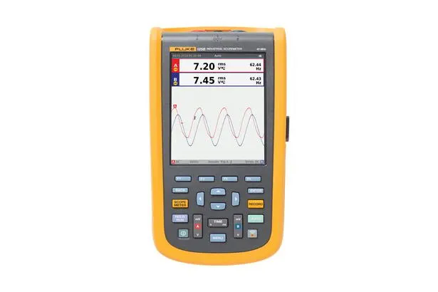
FLUKE 120B
FLUKE P5551
FLUKE P5544
FLUKE P5543