Product Overview
FLUKE 1625-2 KIT (Model 1625-2 KIT) is a FLUKE supplied by Guangzhou Yunke Electronics Co., Ltd. FLUKE 1625-2 KIT — FLUKE · Yunke Electronics. Request a quotation and datasheet.
Brand: FLUKE | Category: FLUKE
Sales Inquiries: 15626018696 · 78403603@qq.com
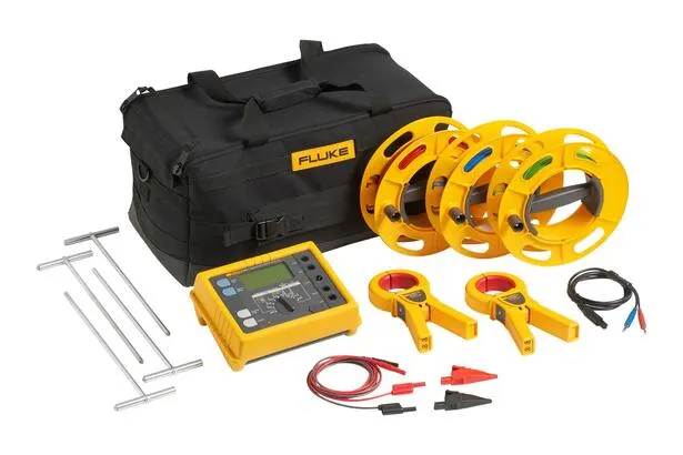
FLUKE 1625-2 KIT
Technical Specifications
| Memory Device | via USB Port can internal Part Memory Device Memory Multi up to 1500 records Recording |
|---|---|
| Measuring Functions | Voltage and Frequency, incl. / excluding Clamp Type Current Device three Extreme and Extreme Grounding Resistance, two Extreme AC Resistance, two Extreme and Extreme DC Resistance |
| Display | 4 Number digits (2999 Number digits) - 7 Range Display (can Property Height) |
| Operation | Centre Rotatable Open and Functions Key |
| Operating Temperature | -10°C to 50°C(14°F to 122°F) |
| Storage Temperature | -30°C to 60°C(-22°F to 140°F) |
| Temperature Coefficient | ± of reading 0.1% / °C 28°C |
| Protection Type | per EN60529, Housing Body IP Rating is IP56; Battery IP Rating is IP40 |
| Maximum Voltage | Warning – Port " Clamp Port " to Port E, ES, S or H |
| Safety | Use Dual Weight and / or plus Insulation Protection. To Ground Maximum 50 V(per IEC61010-1). Pollution Degree 2 |
| Mass Standard | per DIN ISO 9001 Standard Open , Meter and Origin |
| External | Compliant with DIN 43780 (8 / 76) |
| Power Supply | 6 x 1.5 V Alkaline Battery (IEC LR6 or AA Type) |
| Battery Life Range | Operating IEC LR6 / AA Type: General Normal is 3,000 times Measurement (RE+RH ≤ 1 kΩ) |
| Dimensions (Width X Height X Depth) | 250 x 133 x 187 mm (9.75 x 5.25 x 7.35 in) |
| Weight | ≤ 1.1 kg (2.43 lb)(excluding Accessories); 7.6 kg (16.8 lb)( with Case in incl. Accessories and Battery) |
| Housing Material | See the original manufacturer datasheet |
| Measuring Error Extreme Limit: | Full Wave Flow |
| Measuring Range | 1 V to 50 V |
| Display Range | 0.0 V to 50 V |
| Resolution | 0.1 V |
| Frequency Range | AC / DC 45 Hz to 400 Hz Correction Wave |
| Accuracy | ±(of reading 5% + 5 Digits) |
| Measuring Series | Approx. 4 times Measurement / s |
| Internal | Approx. 1.5 MΩ |
| Maximum Overload | Urms = 250 V |
| Measuring Error Extreme Limit: | Measurement Voltage Period |
| Measuring Range | 6.0 Hz to 400 Hz |
| Display Range | 16.0 Hz to 299.9 Hz to 999 Hz |
| Resolution | 0.1 Hz to 1 Hz |
| Range | 1 V to 50 V |
| Accuracy | ±(of reading 1% + 2 Digits) |
| Measuring Method | per IEC61557-5 Standard Use Probe Measurement Current and Voltage |
| Voltage | 20 / 48 V, AC |
| Current | 250 mA(AC) |
| Measuring Frequency | Manual or Automatic Selection 94, 105, 111 and 128 Hz(AFC), at Number R¹ in is 55 Hz |
| Noise | 120 dB(16 2 / 3, 50, 60 and 400 Hz) |
| To Ground Maximum Overload | Urms = 250 V |
| with Error or Quantity | Reference Conditions or Specified Operating Range No. Code per IEC1557 Standard Phase Part Division or Test Test Type |
| with Error | Reference Conditions A No. 5 Part Division 6.1 cells R |
| Digit | Reference Position ±90° E1 No. 1 Part Division 4.2 cells R |
| Supply Voltage | by Manufacturer Gauge Setting Extreme Limit Value E2 No. 1 Part Division 4.2 and 4.3 cells R |
| Temperature | 0°C and 35°C E3 No. 1 Part Division 4.2 cells T |
| Voltage | No. 4.2 and 4.3 cells E4 No. 5 Part Division 4.2 and 4.3 cells T |
| Probe and Grounding Electric Extreme Resistance | 0 to 100 x RA but ≤ 50 kΩ E5 No. 5 Part Division 4.3 cells T |
| Welding Systems Frequency | Nominal Frequency 99% to 101% E7 No. 5 Part Division 4.3 cells T |
| Welding Systems Voltage | Nominal Voltage 85% to 110% E8 No. 5 Part Division 4.3 cells T |
| Operation Error | B = ±(|A| + 1,15 √E²1 E²2 E²3 E²4 E²5 E²6) No. 5 Part Division 4.3 cells R |
| Measuring Range | 0.020 Ω to 300 kΩ |
| Display Range | 0.001 Ω to 2.999 Ω |
| Resolution | 0.001 Ω |
| Accuracy | ±(of reading 2% + 2 Digits) |
| Operation Error | ±(of reading 5% + 5 Digits) |
| Measuring Time | Fixed Frequency when General Normal is 8 s Operating Automatic Frequency Control, Maximum 30 s, with Measurement Frequency Ring |
| by Probe and Grounding Electric Extreme Resistance Additional Error | RH(RS + 2000 Ω) / RE x 1.25 x 10⁻⁶% + 5 Digits |
| RH and RS Measuring Error | Fixed Frequency when General Normal is RE + RS + RH 10% |
| Maximum Probe Resistance | ≤ 1 MΩ |
| Maximum Grounding Electric Extreme Resistance | ≤ 1 MΩ |
| Umeas = 48 V at RH | < 300 Ω |
| Umeas = 20 V at RH | < 250 Ω |
| Resolution | 1 mΩ |
| Measuring Method | per EN61557-5 Standard Use Probe Measurement Current and Voltage, and Use external Pressure Device Measurement Single pcs pcs Circuit in Current. |
| Voltage | 20 / 48 V, AC |
| Current | 250 mA(AC) |
| Measuring Frequency | Manual or Automatic Selection 94, 105, 111 and 128 Hz (AFC), 55 Hz (R¹) |
| Noise | 120 dB(162 / 3, 50, 60 and 400 Hz) |
| To Ground Maximum Overload | To Ground Maximum Urms = 250 V(will not Start-up Measurement) |
| Measuring Range | 0.020 Ω to 300 kΩ |
| Display Range | 0.001 Ω to 2.999 Ω |
| Resolution | 0.001 Ω |
| Accuracy | ±(of reading 7% + 2 Digits) |
| Operation Error | ±(of reading 10% + 5 Digits) |
| by Probe and Grounding Typical Electric Extreme Resistance Additional Error | RH(RS + 2000 Ω) / RETOTAL x 1.25 x 10⁻⁶% + 5 Digits |
| RH and RS Measuring Error | Fixed Frequency when General Normal is RETOTAL + RS + RH 10% |
| Measuring Time | Fixed Frequency when General Normal is 8 s Operating Automatic Frequency Control, Maximum 30 s, with Measurement Frequency Ring. |
| Measure Single Pcs Pcs Minimum Current | 0.5 mA Operating Device (1000:1) |
| Measure Single Pcs Pcs Minimum Current 0.1 mA | Operating Device (200:1) |
| Via Device Maximum Current | 3 A Operating Device (1000:1) |
| Measuring Method | Measurement Current and Voltage |
| Measuring Voltage | 20 V AC Voltage, |
| Current | > 250 mA(AC) |
| Measuring Frequency | Manual or Automatic Selection 94, 105, 111 and 128 Hz (AFC) |
| Measuring Range | 0.020 Ω to 300 kΩ |
| Display Range | 0.001 Ω to 2.999 Ω |
| Resolution | 0.001 Ω |
| Accuracy | ±(of reading 2% + 2 Digits) |
| Operation Error | ±(of reading 5% + 5 Digits) |
| Measuring Time | General Normal is 6 s |
| Maximum Voltage | 24 V, Over Over 24 V No Start-up Measurement |
| Maximum Overload | Urms Maximum = 250 V |
| Measuring Method | can per IEC61557-4 Current - Voltage Measurement |
| Measuring Voltage | DC 20 V |
| Current | 250 mA DC |
| Measuring Value Type | to at Extreme Measurement, can Length H, S, ES Test Lead and not Origin Additional Error. / Test Lead E in Resistance > 1 Ω when, can Guide 5m Ω / Ω Additional Error. |
| Measuring Range | 0.020 Ω to 300 kΩ |
| Display Range | 0.001 Ω to 2.999 Ω |
| Resolution | 0.001 Ω |
| Accuracy | ±(of reading 2% + 2 Digits) |
| Operation Error | ±(of reading 5% + 5 Digits) |
| Measuring Series | Approx. 2 times Measurement / s |
| Measuring Time | General Normal is 4 s, Package Extreme Property Rotation (two Extreme or Extreme) |
| Maximum Voltage | DC or AC Voltage ≤3 V, Over Over 3 V No Start-up Measurement |
| Maximum Rate | 2 Henry |
| Maximum Overload | Urms = 250 V |
| Measuring Value Type | R Display = R Measurement - R Compensation ² |
| Level Digit | RA Extreme (Dual Clamp Port, No ) |
| Resolution | 0.001 Ω to 0.1 Ω |
| Measuring Range | 0.02 Ω to 199.9 Ω |
| Accuracy | ±(of reading 7% + 3 Digits) |
| Operation Error | ±(of reading 10% + 5 Digits) |
| Measuring Voltage | Vm = 48 V AC ( class Voltage) |
| Measuring Frequency | 128 Hz |
| Noise Current (IEXT) | Maximum IEXT = 10 A(AC)(RA < 20 Ω) |
Some specification lines are quoted from the original manufacturer datasheet. Numbers, units and model codes are preserved verbatim; an English datasheet is available on request.
Product Description
Product Overview
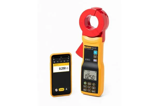
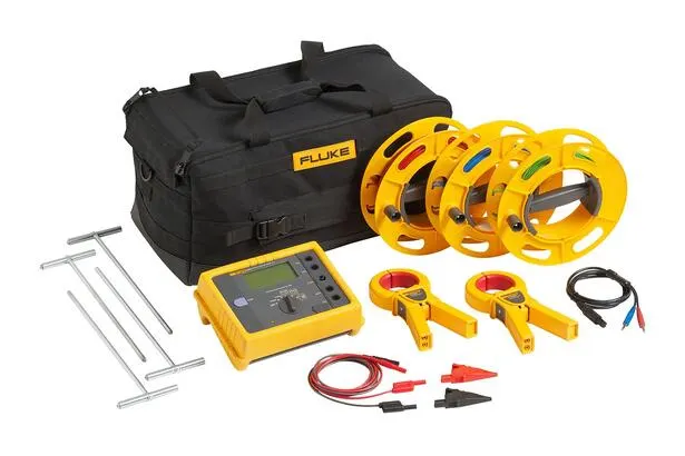
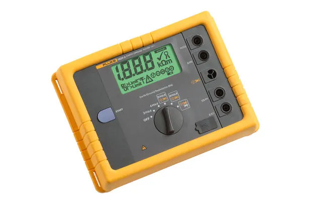
The untied test Fluke 1625-2 KIT ground resistance test machine is used to measure the ground circuit resistance only with a plier. Put two clamps on the baton, each of which is connected to the test. No need to use the plier. One of the pliers is known to be fixed and the other to measure the current. Then the tester automatically determines the resistance of the plier..Pngs are known to be fixed and the other plier to measure the current. Then, the tester automatically determines the resistance of the punt. This test method is only applied in the case of a site system in the building or building under observation, although it is the case in most cases. if there is only one access point, as is used in many residential applications, no test method can provide an acceptable value._ When a test is taken, it is not necessary to break the stick - it is sufficient to maintain the integrity of the combined system in the test. it is no longer necessary to spend time putting and connecting the ground poles on the system. You can also perform site tests, including inside buildings, cable towers, or any location where you cannot access the land.?_._. The full-scale tester Fluke 1625-2 KIT is a unique ground tester._ All four types of feed can be completed: Tripodes and quadruple-level reduction (using earthmarks) 4polar soil resistance tests (using earthmarks) Selective tests (using earthmarks and 1 pliers) No test (only so) Use 2 plier)Screaks
Key Advantages
- Triode and quadruple drop-down ground resistance circuit tests
- Four-polar soil resistance testCharlie
- Selective ground rod test using 1 pliersScrets
- Unplugged ground rod test using 2 pliers
- IP56 Protection Level for outdoor use
- Hard carry box
- USB Data Storage and Transfer
Category Description
Measurement of resistance to ground systems for mine detection, electrical installation acceptance and periodical testing.AssScrells
Applied industry & test project
- Industry: Ground-based systems testing, electrical installation, mine detection, electrical engineering
- Applications: tripo and quadruple-level drop-down ground resist circuit tests; tetrapolar soil resistivity tests; selective ground rod tests using 1 pliers
FAQ
Q: What can FLUKE Fluke 1625-2 KIT do with the main features of the substation resistance test? Q: Q: Q: Q: Q: Q1 Fluke 1625-2 KIT Q: What can Quasi test system for ground resistance test? Q: What can Qu? Q?
A: FLUKE Fluke 1625-2 KIT ground resister tester is a ground resister test product for FLUKE Fluke. Q. XOXT QT QT TT T The main functions listed officially include: a triode and quadruple-level drop-off ground resist circuit test; a tetrapolar soil resistance test; and a selective ground rod test using 1 pliers. Survey object and process requirements can be provided and confirmed with cloudy assistance
Q: What are the key technical indicators for 1625-22? Q: What are the key technical indicators? Q: Q: Q: Q: Q: Q: Q: Q: Q:. Reference: KIT. Reference values: 2.
A: This page parameter table has been compiled by official information and contains a total of 120 items,.A.Signatures For more detailed accuracy and environmental conditions, please refer to the official manual, and please refer to the official manual. This page is not open article by article.!. Reference: 0 V, UST
Q: How can the selection and the cargo date be confirmed?!
A: Guangzhou Yunke Electronics Co., Ltd. supplies a full range of FLUKE Fluke products, which can provide selective advice, technical information and post-sale support. Please provide a specific model, quantity and usage profile, which will be confirmed with the assistance of staff
Q: What is the type of substation resistance test for FLUKE Fluke 1625-2 KIT? What are the scenarios?
A: This product belongs to the Ground Resistance Test (FLUKE Fluke/ Ground Resistance Test). to measure the resistance of the ground system for mine detection, electrical installation and periodical testing
Q: How can technical support be obtained after purchase?!
A: Products with official instructions and quality assurance services; Guangzhou Yunke Electronics Co., Ltd. provides pre-sale selection and post-sale coordination services, which can be submitted through site contact, supported by staff assistance to connect to the original plant
All model codes, numbers and units are preserved verbatim from the original manufacturer datasheet. An English datasheet is available on request.
For a quotation, lead time or an optional calibration certificate, please contact our engineers.